")

Description
Terminal number description/action
1 and 3X1/X2 supply voltage input
8. 9 and 10
(“P <5%”) After splitting (shorting terminals 33 and 34 ("Unl")), a disconnection signal will be sent to the generator switch when the power is less than 5% Pn. 13. 14 and 15 (“-P >5/10%
5 s/10 s”)
Relay output for reverse power protection- P> The set point of is set by DEIF, – P>5% (delay: 5s or 10s) or P>10% (delay: 5s or 10s).
17 and 18
Sta
Status output: it is activated (closed) when the working power supply is normal and the unit is normal.
28 and 29
IL1
Current measurement input. Note that the S1 terminal of the external current transformer is connected to terminal 28, and S2 is connected to terminal 29.
31 and 32
Ext. P.
If an internal power transmitter is used (normal), this terminal is shorted.
For unbalanced load applications, it is recommended to use an external power transmitter (instead of an internal power transmitter). Connect external power transmitter to 31
(+) and 32 (-). The output of the external transmitter must be 4… 20 mA DC. The output of the connected transmitter must be limited to a minimum of 2
MA and 22 mA maximum. It is recommended to use the DEIF transmitter TAS-331DG.
33 and 34
(“Unl”)
It can be connected to the normally open contact of the relay. When this contact is activated, the power of the generator is adjusted to zero (splitting) and LSU113DG disconnects the PS power line.
thirty-five
(“Ref.”)
Reference input. If not used, it must be connected to terminal 36 (“”).
This input is used to control the operation of the power unit in the power control mode (fixed load to the grid). One+0.5 V… 5
The signal input of V reference will control the PU within the range of 10… 100% power. This input is active at 0.55V and invalid at 0.45V.
Note that when this input is active, the LSU-113DG is still connected to the PS and FS lines. In this mode, the PS line is used as an output.
thirty-seven
(“+5V”)
Reference output. The voltage output can be used in the local power control mode.
If terminal 37 is used as a voltage divider, and the output of the voltage divider is connected to terminal 35, local power control can be performed.
thirty-six
(“”)
The common ground terminal of the above reference input and output.
38 (FS) and
39 (“”)
Frequency distribution line of connected LSU-113DG.
40 (PS) and
41 (“”)
The power distribution line of the connected LSU-113DG. Normally 5 V is displayed at the rated busbar voltage and cos phi=1. If the label says cos
Phi 0.8, 4 V corresponds to 100% power.
43 and 44
Relay contact
“SG”
Relay contact for speed increase
45 and 46
Relay contact
“SG”
Relay contact for speed reduction
be careful:
relay
contact
When applied to DC servomotors, the relay (SG) shall be connected to an external auxiliary relay.
The coil of the external relay shall be connected with a transient suppressor.

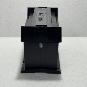
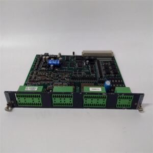
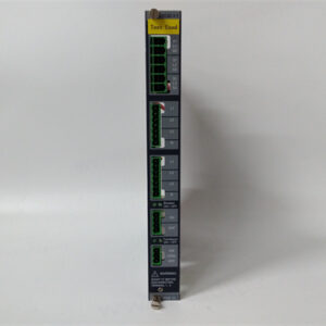
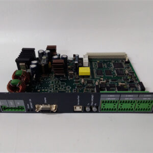
LSU-113DG


All prices listed on the official website are subject to confirmation by contact: Wu Jiedong (manager).
Our product: brand new original packaging
Our warranty: All new or repaired parts have a 12 month warranty period beginning
Our payment: 100% telegraphic transfer of inventory items before shipment, conditions can be proposed!
If you have any downtime spare parts that you cannot find, please feel free to call or use email to contact me. If there are issues that the product cannot solve, please contact me. Product prices can be negotiated. Please do not consider contacting me!